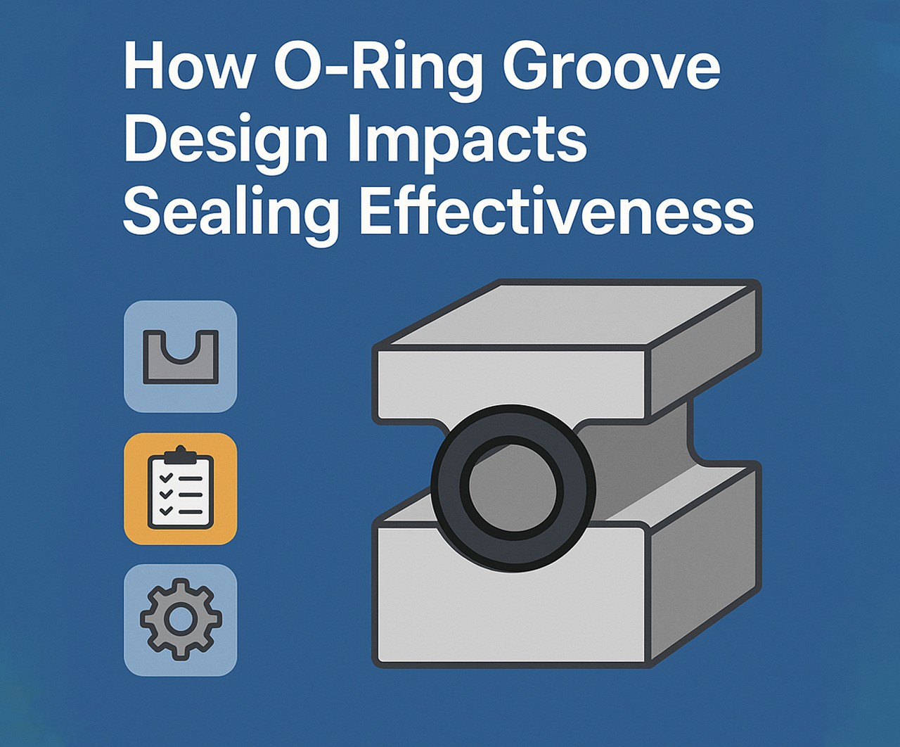
When engineers evaluate the reliability of sealing systems, three core components often come into play: the ring seal, the seal ring, and the bearing seal. While material selection and operating conditions receive plenty of attention, the overlooked hero in this trio is groove design. The groove—where the O-ring sits—serves as the stage on which the sealing performance unfolds. A poorly designed groove can undermine even the best O-ring, causing leaks, extrusion, or early failure. This article dives into why O-ring groove design matters, how it affects the performance of the ring seal, and what engineers need to consider when developing or troubleshooting high-stakes sealing systems. Know more..
O-ring grooves (also called glands) are precision-cut channels into which O-rings are installed. These grooves control compression, stretch, and movement of the O-ring under load. Proper groove geometry ensures that the seal ring maintains consistent contact with its mating surface to prevent leaks and withstand pressure.
The Basics of O-Ring Groove Design
Groove design must consider:
- Groove depth
- Groove width
- Surface finish
- Material compatibility
- Temperature and pressure conditions
Why Groove Design Affects Seal Integrity
O-rings function by deforming under pressure, creating a tight seal between two surfaces. The shape and size of the groove influence how well the O-ring can compress and rebound during operation. A groove that is too deep or too shallow can lead to:
- Over-compression: Causes permanent deformation or cracking of the ring seal
- Under-compression: Allows leaks or reduces the sealing force
- Extrusion: If the groove clearance is too wide, the O-ring can be forced out under pressure
In dynamic applications like rotating shafts or reciprocating pistons, improper groove design can also increase friction and wear, particularly in bearing seal applications.
Static vs. Dynamic Groove Design
Static Sealing
Static sealing involves two non-moving surfaces. Groove design here focuses on:
- Adequate squeeze (compression) of the O-ring
- Correct width to accommodate thermal expansion
- Compatibility with lubricants or sealants
Common applications: Electrical enclosures, flanged pipe connections, lid seals
Dynamic Sealing
Dynamic applications include linear or rotary motion. Groove design for seal rings in dynamic systems must also account for:
- Minimizing friction and wear
- Preventing rolling or twisting of the O-ring
- Managing lubrication in the groove
Common applications: Hydraulic cylinders, gearboxes, bearing seals
The Role of Groove Geometry
Groove geometry determines the deformation behavior of the O-ring. Important factors include:
1. Groove Depth
Controls how much the O-ring compresses. Typically, 10–30% squeeze is desired depending on the material.
2. Groove Width
Provides room for the O-ring to expand under compression and thermal changes. Inadequate width causes pinching; excessive width can cause rolling or flipping.
3. Groove Radius
Sharp corners create stress points. A small fillet radius at the base of the groove distributes stress and extends ring seal life.
4. Surface Finish
A smoother finish (Ra 8–16 µin) helps prevent abrasion, especially in bearing seal systems under dynamic movement.
Best Practices for Groove Design
- Use standard O-ring sizes: Stick to AS568 (imperial) or ISO 3601 (metric) standards for easier sourcing and consistency.
- Mind the squeeze: Adjust groove depth and width to achieve the recommended compression based on material hardness and application.
- Temperature effects: Account for thermal expansion of both the O-ring and the groove material.
- Vent the groove: In static face seals, grooves should allow air to escape during installation to avoid pressure traps.
How Groove Design Affects Bearing Seal Performance
In bearing seals, O-ring grooves are crucial to preventing lubricant leakage and contaminant ingress. Bearings often experience rotational or oscillatory motion, and the seal groove must be optimized to:
- Keep the seal ring in position during high-speed rotation
- Withstand heat generated by friction
- Manage pressure variations due to speed changes or thermal cycling
Improper groove design in a bearing seal can result in lubricant loss, overheating, or component wear.
Case Study: Hydraulic Cylinder Groove Failures
A manufacturer experienced repeated ring seal blowouts in their hydraulic cylinders. Investigation revealed:
- Groove depth was too shallow, leading to over-compression
- Edges of the groove had burrs that nicked the O-ring during installation
Fixes included:
- Redesigning the groove to meet ISO 3601 standards
- Adding radiused corners to the groove
- Switching to a more extrusion-resistant O-ring material
The changes improved seal lifespan by 3x and reduced downtime by 40%.
Tools and Technologies for Better Groove Design
Modern engineering tools allow precision groove design:
- FEA (Finite Element Analysis): Simulates how an O-ring behaves in its groove under various loads
- CAD-integrated groove libraries: Include standard and custom groove profiles
- 3D printing: For rapid prototyping and testing of custom groove configurations
Some O-ring manufacturers offer free online groove calculators to help engineers get it right.
Innovations in Groove + O-Ring Integration
- Asymmetric grooves: Improve sealing under uneven pressure conditions
- Smart grooves: Designed with embedded sensors to monitor seal condition
- Self-energizing seal rings: Groove designs that use system pressure to enhance sealing force
These innovations are particularly useful in aerospace, medical, and automotive sealing systems.
Groove Design for Harsh Environments
In harsh environments like offshore drilling or space, groove design becomes even more critical. Engineers must consider:
- Material compatibility with corrosive fluids
- Wide temperature swings
- High-frequency vibration (especially in bearing seal grooves)
- Pressure differentials that may reverse direction
Custom seal grooves paired with high-performance seal rings can prevent catastrophic failure in these settings.
Maintenance Implications
Poor groove design leads to frequent O-ring replacements. By contrast, a well-designed groove:
- Reduces installation errors
- Increases time between maintenance cycles
- Minimizes leakage and contamination risk
- Technicians also benefit from easier troubleshooting when groove dimensions match standard specs.
Final Thoughts: Design the Groove, Seal the System
A flawless sealing system isn’t just about selecting the right ring seal, seal ring, or bearing seal. It’s about designing the groove that allows these components to perform at their best. In fact, groove design is the bridge between theoretical seal performance and real-world results.
If you’re designing for high-speed rotation, fluctuating pressure, or extreme environments, take time to engineer your groove as thoughtfully as your material. In many cases, a redesign of the groove—not the seal itself—is the key to eliminating failures and improving system longevity.
So next time a seal ring fails, look beyond the rubber. The secret may be hiding in the groove.


